
This 650 MHz clock module receives RF signal at 1300MHz from a master oscillator using a bi-directional coupler. The forward and reflected signals are processed to eliminate any phase drifts due to temperature changes in the environment. In a similar way RF signal of 325MHz is an input to the clock module through a bi-directional coupler. The forward and reflected signals are processed to eliminate any phase drifts due to temperature changes in the environment.
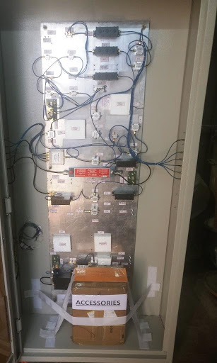
Suitable Clock dividers are present in the clock module to generate clock frequencies of 20MHz from 1300MHz. Using mixers, 1320MHz and 670MHz RF signals are generated from 1300MHz and 650MHz input RF signals respectively. 650MHz, phase stabilized RF reference signal is generated using a PLL from 650MHz input signal. The entire clock module is enclosed in a temperature controlled chassis to eliminate phase drifts of the components due to temperature changes in the environment. All the RF components are with connectors and phase stabilized cables are used to interconnect the components.
650 MHz clock module contains a number of RF signal processing modules, which includes Bi-directional couplers, attenuators, power splitters, band-pass filters, frequency multipliers, frequency mixers, high frequency amplifiers, phase shifters, clock distribution ICs, operation amplifiers etc to generate phase reference signals to various sub systems at different frequencies in an accelerator system.
The module has three different functions defined as follows:-
- Generate 1320MHz RF signal from 1300MHz RF input to the module
- Generate 670MHz RF signal from 650MHz RF input to the module
- Generate 650MHz phase stabilized RF signal from 325MHz RF input to the module using PLL
Inputs and outputs of the clock module are given below
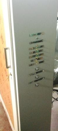
A. RF inputs to the clock module on instrumentation bin:
- 1300MHz RF signal on SMA connector
- 325MHz RF signal on SMA connector
- 650MHz RF signal on SMA connector
- Control signal for temp. stability
- 230V,AC input
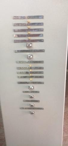
B. Outputs from the clock module on the instrumentation panel
- 1300MHz on SMA connector 4no:s
- 1320MHz on SMA connector 1no;s
- 670MHz on SMA connector 1no
- 650MHz on SMA connector 4no:
- 325 MHz on SMA connector 1no:
- Temp. sensor output.
THIS HAS BEEN DEVELOPED MUMBAI FOR IIFC COLLABORATION, US REQUIRED IN ACCELERATOR CONTROL APPLICATION.
Subscribe Newsletter
A quick message to TECHNID
Client Speaks
Lorem Ipsum is simply dummy text of the printing and ty . . .
Lorem Ipsum is simply dummy text of the printing and ty . . .
Lorem Ipsum is simply dummy text of the printing and ty . . .
This 650 MHz clock module receives RF signal at 1300MHz from a master oscillator using a bi-directional coupler. The forward and reflected signals are processed to eliminate any phase drifts due to temperature changes in the environment. In a similar way RF signal of 325MHz is an input to the clock module through a bi-directional coupler. The forward and reflected signals are processed to eliminate any phase drifts due to temperature changes in the environment.
Suitable Clock dividers are present in the clock module to generate clock frequencies of 20MHz from 1300MHz. Using mixers, 1320MHz and 670MHz RF signals are generated from 1300MHz and 650MHz input RF signals respectively. 650MHz, phase stabilized RF reference signal is generated using a PLL from 650MHz input signal. The entire clock module is enclosed in a temperature controlled chassis to eliminate phase drifts of the components due to temperature changes in the environment. All the RF components are with connectors and phase stabilized cables are used to interconnect the components.
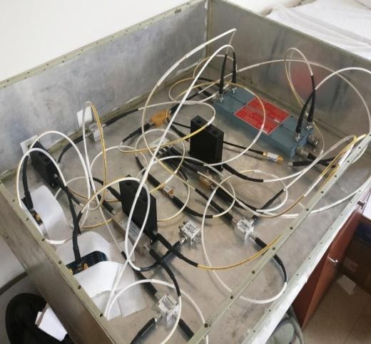
650 MHz clock module contains a number of RF signal processing modules, which includes Bi-directional couplers, attenuators, power splitters, band-pass filters, frequency multipliers, frequency mixers, high frequency amplifiers, phase shifters, clock distribution ICs, operation amplifiers etc to generate phase reference signals to various sub systems at different frequencies in an accelerator system.
The module has three different functions defined as follows:-
- Generate 1320MHz RF signal from 1300MHz RF input to the module
- Generate 670MHz RF signal from 650MHz RF input to the module
- Generate 650MHz phase stabilized RF signal from 325MHz RF input to the module using PLL
Inputs and outputs of the clock module are given below

A. RF inputs to the clock module on instrumentation bin:
- 1300MHz RF signal on SMA connector
- 325MHz RF signal on SMA connector
- 650MHz RF signal on SMA connector
- Control signal for temp. stability
- 230V,AC input