
Following are the main features of the product :-
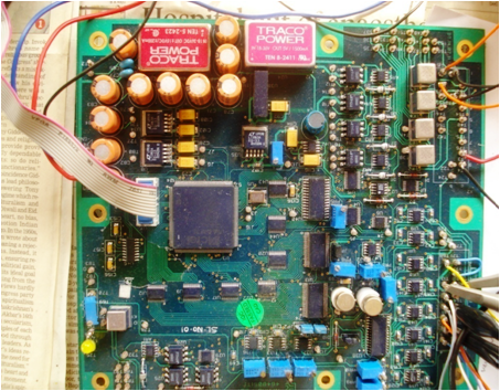
- Firmware design for FPGA based NRHO module has been designed and developed for linear neutron flux signal generation and continuous real time reactivity monitoring using A3PE3000 (3 Million Actel FPGA).
- Linear neutron flux signal is being computed for all the seven pulse ranges and six analog voltage ranges (N1-N6)with response time between 100µs to 500ms . Brange output will indicate the neutron flux range.
- Moving average filter is used for computation of neutron flux signal in the pulse range and in the linear range.
- Reactivity signal is being computed only in the linear range within FPGA using linear neutron flux signal for analog voltage ranges N1 to N6 using Digitized INVERSE POINT KINETIC EQUATIONS FOR NUCLEAR REACTOR AS POINT MODEL WITH NO SPATIAL FLUX VARIATIONS.
- The analog output of the computed reactivity is generated using an external DAC with a response time less than 500ms.
- The range of reactivity is -5β to +1β with accuracy within ±0.2β and ±0.1β for specified ranges.
- Response time for both the signal generations can be controlled remotely using RS232 Interface.
- Online diagnostic features include ADC stuck bit check, Analog Neutron Flux check, Analog Reactivity Check, ADC Reference voltage check, Floating Point Exception Check, Flow Control Check and Pseudo Reactivity Computation Cycle check. Their data is sent online through RS232 interface on the PC.
- FPGA Requirement Specification Document(FRS), FPGA Code Architecture Document(FCAD), FPGA Design Document (FCDD)and FPGA Test Bench Document (FTBD) are generated for the entire design in stage-wise review by the client and for subjecting the code for formal verification and validation. â¦
- VHDL code design for NRHO is completed and tested on the hardware with hardware test reports. FRS and FCAD are generated and approved by the client.
- FCDD includes tool generated VHDL parsed flow-charts and SMs for clear functional understanding of each module.
- Software test benches have been generated for leaf level and integrated design to test the functionality against already generated expected reference vectors and the test results are logged for customer review.
- Entire test bench generation, comparison and data logging operations have been done using software with no human intervention.
- Hardware testing of the entire code along with the documentation has been done on-site at HYDERABAD on 5 modules developed by them.
FOLLOWING IS THE BRIEF ABOUT THE DOCUMENTS BEING GENEARATED:-
- FPGA Specification Documents
- Functional Description with Block level details
- Timing and Performance requirement.
- External Interface requirements and Physical Design Issues.
- Design Constraints and Traceability
- FPGA Code Architecture Document
- Major VHDL modules of FPGA involved to achieve the functionalities and algorithms mentioned in earlier document.
- Inter-connecting signals between VHDL modules and with the FPGA I/Os
- VHDL Code Design Document
- VHDL Entity Block diagram
- VHDL Entity Interface signal description (type, functionality and interconnection with other entities in the design)
- Functional description of entity
- Tool generated Editable Flow Charts / State Diagram
- VHDL Test Bench Document
- This document describes the test scenarios applied to each and every entity of the VHDL design involved in the NRHO development, the set of the input test vectors on the UUT and the expected results of the UUT.
- List files for functional simulation from the MODELSIM-ACTEL have been generated for all the leaf level, trunk level and higher level entities to establish the same.
- Statement coverage of each entity has been derived and documented with reasoning in case not reaching to 100% code coverage.
- Well Documented Test Bench files for leaf level, intermediate and top level HDL design files indicating error reports and percentage statement coverage in code coverage.
THIS HAS BEEN DEVELOPED HYDERABAD FOR NUCLEAR INSTRUMENTATION TYPE MREACTOR INSTRUMENTATION APPLICATION
Subscribe Newsletter
A quick message to TECHNID
Client Speaks
Lorem Ipsum is simply dummy text of the printing and ty . . .
Lorem Ipsum is simply dummy text of the printing and ty . . .
Lorem Ipsum is simply dummy text of the printing and ty . . .


Features
- Firmware design for FPGA based NRHO module has been designed and developed for linear neutron flux signal generation and continuous real time reactivity monitoring using A3PE3000 (3 Million Actel FPGA).
- Linear neutron flux signal is being computed for all the seven pulse ranges and six analog voltage ranges (N1-N6)with response time between 100µs to 500ms . Brange output will indicate the neutron flux range.
- Moving average filter is used for computation of neutron flux signal in the pulse range and in the linear range.
- Reactivity signal is being computed only in the linear range within FPGA using linear neutron flux signal for analog voltage ranges N1 to N6 using Digitized INVERSE POINT KINETIC EQUATIONS FOR NUCLEAR REACTOR AS POINT MODEL WITH NO SPATIAL FLUX VARIATIONS.
- The analog output of the computed reactivity is generated using an external DAC with a response time less than 500ms.
- The range of reactivity is -5β to +1β with accuracy within ±0.2β and ±0.1β for specified ranges.
- Response time for both the signal generations can be controlled remotely using RS232 Interface.
- Online diagnostic features include ADC stuck bit check, Analog Neutron Flux check, Analog Reactivity Check, ADC Reference voltage check, Floating Point Exception Check, Flow Control Check and Pseudo Reactivity Computation Cycle check. Their data is sent online through RS232 interface on the PC.
- FPGA Requirement Specification Document(FRS), FPGA Code Architecture Document(FCAD), FPGA Design Document (FCDD)and FPGA Test Bench Document (FTBD) are generated for the entire design in stage-wise review by the client and for subjecting the code for formal verification and validation. â¦
- VHDL code design for NRHO is completed and tested on the hardware with hardware test reports. FRS and FCAD are generated and approved by the client.
- FCDD includes tool generated VHDL parsed flow-charts and SMs for clear functional understanding of each module.
- Software test benches have been generated for leaf level and integrated design to test the functionality against already generated expected reference vectors and the test results are logged for customer review.
- Entire test bench generation, comparison and data logging operations have been done using software with no human intervention.
- Hardware testing of the entire code along with the documentation has been done on-site at HYDERABAD on 5 modules developed by them.

Features
- FPGA Specification Documents
- Functional Description with Block level details
- Timing and Performance requirement.
- External Interface requirements and Physical Design Issues.
- Design Constraints and Traceability
- FPGA Code Architecture Document
- Major VHDL modules of FPGA involved to achieve the functionalities and algorithms mentioned in earlier document.
- Inter-connecting signals between VHDL modules and with the FPGA I/Os
- VHDL Code Design Document
- VHDL Entity Block diagram
- VHDL Entity Interface signal description (type, functionality and interconnection with other entities in the design)
- Functional description of entity
- Tool generated Editable Flow Charts / State Diagram
- VHDL Test Bench Document
- This document describes the test scenarios applied to each and every entity of the VHDL design involved in the NRHO development, the set of the input test vectors on the UUT and the expected results of the UUT.
- List files for functional simulation from the MODELSIM-ACTEL have been generated for all the leaf level, trunk level and higher level entities to establish the same.
- Statement coverage of each entity has been derived and documented with reasoning in case not reaching to 100% code coverage.
- Well Documented Test Bench files for leaf level, intermediate and top level HDL design files indicating error reports and percentage statement coverage in code coverage.