
.jpg)
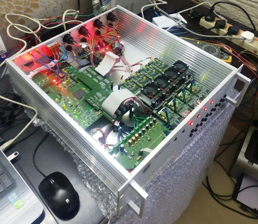
THIS IS A CYCLONE V SX SOC BASED ANSI VITA ELECTRICAL COMPLIANT RF CAVITY RESONANCE CONTROL SYSTEM IS ACCOMMODATED IN A SINGLE 2U/3U, 19” CHASSIS AND CONSISTS OF FOLLOWING ELECTRONIC MODULES/BOARDS VIZ;
GENERAL PURPOSE FPGA CARD HAVING THE FOLLOWING FEATURES:-
- High Speed, high density FPGA with 110K logic elements, 3.125Gbps transceivers (Nos. 9), integrated Dual-core hard processor system up to 800 MHz maximum frequency.
- 670 MHz clock input, 400MHz interconnect frequency with support for symmetric and asymmetric multiprocessing in 896 FBGA package with the fastest speed grade available.
- 1 number of IEEE 802.3 based Gigabit Ethernet support using RGMII MAC compliant with 1000BASE-T specifications using CAT5 UTP cable or better.
- 4 numbers of Duplex Hot Pluggable IEEE 802.3AH based Gigabit Ethernet support compliant with 1000BASE-SX PMD Specifications, SFP SMA using Multimode Fibre up to 500m.
- Using SFP, Card can act as White Rabbit Node using SYNCE and PTP in a large network.
- ANSI VITA 57.1 based FMC connectors for interfacing with Mezzanine Ultra high speed ADC-DAC Card and other various cards using SERDES interface. Control of Mezzanine Card peripherals like ADC, DAC, Clock using SPI and I2C Control.
- Ultra low noise and sub ps jitter on board Clock generation using DAC controlled VCXO and VCO. Clock configurable between LVPECL, LVDS [625 MHz] and LVCMOS [250 MHz].
- Clock selection between ON-Board Clock generation and Clock coming from Mezzanine Card.
- 400MHz, 1Gbyte DDR3 with EEC support on HPS side.
- Accommodates boot options such as SD/MMC, QSPI using HPS.
- USB2.0 OTG Interface for transfer of data to a remote system or a storage device.
- 64Mbyte QSPI FLASH for HPS boot
- μSD slot connected to HPS for UBOOT and LINUX booting. Complete BSP has been provided for testing each and every interface.
- EEPROM for general Solid State storage, 32Kbits
- JTAG interface and MICTOR Connector for FPGA and or HPS side debugging.
- On board Very high speed 250 MSPS DAC for debugging purpose.
- On board RTC.
- 25 MHz HPS clock
- 1MHz and 50MHz clock oscillators.
- Highly advanced and extremely low noise PMBUS controlled power architecture with voltage monitors on every DC to DC Converter output in Servo Controlled Loop Mechanism.
- Test codes for all the various interfaces along with Linux boot up image.
It can generate necessary drive sequence to drive four stepper motors or it can also receive commands from external master processes them and generate necessary drive sequence to drive four stepper motors.
- No. of channels : 4
- Interface to external master through SPI interface.
- Can also be controlled through PC using USB interface by using on board USB to UART bridge.
- Suitable MAX V CPLD is used to generate necessary sequence for stepper motor.
- Stepper Motor Drive current 2A.
- Stepper Motor Operating Voltage 8.0V to 60.0V
- Adjustable limiting current
- Over current, Over temperature protection.
- Back EMF monitoring
- Micro-stepping feature ( down to 1/256 step)
- Interfaces with external limit switches 4 numbers for external control
- Generates 2.5KV isolated signals for field communication through suitable isolators and DC to DC converters
- Control Electronics works @ 12V.
- Drive Electronics work at 8.5V to 60V.
- Test Codes provided for all important interfaces.
PIEZO DRIVE CARD, CONTROLLED BY THE FPGA CARD, CONSISTS OF TWO BOARDS VIZ; PIEZO CARRIER BOARD AND MEZZANINE PIEZO AMPLIFIER BOARD. THE MODULE SUPPORTS TUNING OF ONE RESONANT CAVITY.
PIEZO CARRIER CARD
- Provision for mounting Piezo amplifier board
- True 18-Bit, Voltage Output DAC with1μs settling time and SPI / QSPI / MICROWIRE interface.
- 8-Channel DAS with 18-Bit, Bipolar, Simultaneous Sampling ADC (200ksps at all channels), with high speed serial and parallel interface.
- Drive Voltage, output Voltage and current monitoring by High Common-Mode Voltage Difference Amplifier via 18 bit ADC.
- Analog control and monitor through front panel TRS jacks.
- Quad-Channel Digital Isolators.
PIEZO MEZANNINE CARD
Each board is three channels, ultra-low Noise Miniature 150V Piezo Driver. It is a complete miniaturized power supply and ultra-low noise driver for up to three 100V, 120V or 150V piezoelectric stack actuators with following features:-
- RMS current per channel: 78mA
- Signal BW: 180KHz
- Gain: 20
- Slew rate: 38V/μs
Dimension: 76 x 40 x 44 mm (L x W x H)
FIELD MEZZANINE BASED BREAKOUT CARD WHICH INTERFACES FPGA CARD WITH STEPPER MOTOR CARD AND PIEZZO DRIVER CARD.
POWER CARD FOR POWER DISCTRIBUTION AND FILTERING OF ALL THE POWER SUPPLIES.
Applications:- Low Level RF Detection in Accelerator Control Application.
Subscribe Newsletter
A quick message to TECHNID
Client Speaks
Lorem Ipsum is simply dummy text of the printing and ty . . .
Lorem Ipsum is simply dummy text of the printing and ty . . .
Lorem Ipsum is simply dummy text of the printing and ty . . .
.jpg)
THIS IS A CYCLONE V SX SOC BASED ANSI VITA ELECTRICAL COMPLIANT RF CAVITY RESONANCE CONTROL SYSTEM IS ACCOMMODATED IN A SINGLE 2U/3U, 19” CHASSIS AND CONSISTS OF FOLLOWING ELECTRONIC MODULES/BOARDS VIZ;
GENERAL PURPOSE FPGA CARD HAVING THE FOLLOWING FEATURES:-
- High Speed, high density FPGA with 110K logic elements, 3.125Gbps transceivers (Nos. 9), integrated Dual-core hard processor system up to 800 MHz maximum frequency.
- 670 MHz clock input, 400MHz interconnect frequency with support for symmetric and asymmetric multiprocessing in 896 FBGA package with the fastest speed grade available.
- 1 number of IEEE 802.3 based Gigabit Ethernet support using RGMII MAC compliant with 1000BASE-T specifications using CAT5 UTP cable or better.
- 4 numbers of Duplex Hot Pluggable IEEE 802.3AH based Gigabit Ethernet support compliant with 1000BASE-SX PMD Specifications, SFP SMA using Multimode Fibre up to 500m.

- Using SFP, Card can act as White Rabbit Node using SYNCE and PTP in a large network.
- ANSI VITA 57.1 based FMC connectors for interfacing with Mezzanine Ultra high speed ADC-DAC Card and other various cards using SERDES interface. Control of Mezzanine Card peripherals like ADC, DAC, Clock using SPI and I2C Control.
- Ultra low noise and sub ps jitter on board Clock generation using DAC controlled VCXO and VCO. Clock configurable between LVPECL, LVDS [625 MHz] and LVCMOS [250 MHz].
- Clock selection between ON-Board Clock generation and Clock coming from Mezzanine Card.
- 400MHz, 1Gbyte DDR3 with EEC support on HPS side.
- Accommodates boot options such as SD/MMC, QSPI using HPS.
- USB2.0 OTG Interface for transfer of data to a remote system or a storage device.
- 64Mbyte QSPI FLASH for HPS boot
- μSD slot connected to HPS for UBOOT and LINUX booting. Complete BSP has been provided for testing each and every interface.
- EEPROM for general Solid State storage, 32Kbits
- JTAG interface and MICTOR Connector for FPGA and or HPS side debugging.
- On board Very high speed 250 MSPS DAC for debugging purpose.
- On board RTC.
- 25 MHz HPS clock
- 1MHz and 50MHz clock oscillators.
- Highly advanced and extremely low noise PMBUS controlled power architecture with voltage monitors on every DC to DC Converter output in Servo Controlled Loop Mechanism.
- Test codes for all the various interfaces along with Linux boot up image.
.jpg)
It can generate necessary drive sequence to drive four stepper motors or it can also receive commands from external master processes them and generate necessary drive sequence to drive four stepper motors.
- No. of channels : 4
- Interface to external master through SPI interface.
- Can also be controlled through PC using USB interface by using on board USB to UART bridge.
- Suitable MAX V CPLD is used to generate necessary sequence for stepper motor.
- Stepper Motor Drive current 2A.
- Stepper Motor Operating Voltage 8.0V to 60.0V
- Adjustable limiting current
- Over current, Over temperature protection.
- Back EMF monitoring
- Micro-stepping feature ( down to 1/256 step)
- Interfaces with external limit switches 4 numbers for external control
- Generates 2.5KV isolated signals for field communication through suitable isolators and DC to DC converters
- Control Electronics works @ 12V.
- Drive Electronics work at 8.5V to 60V.
- Test Codes provided for all important interfaces.
.jpg)
.jpg)